In general, creating an axonometric view is probably easiest in Rhino using a script. However, if you want to go over the process step by step and also learn how to export your axonometric view, read on.
Learning how to export will be perfect if you are creating other drawings too such as a two point perspective as the process of exporting using the “Make2D” command which you will see is the same for all drawings.
contents
How to create an axonometric view in Rhino
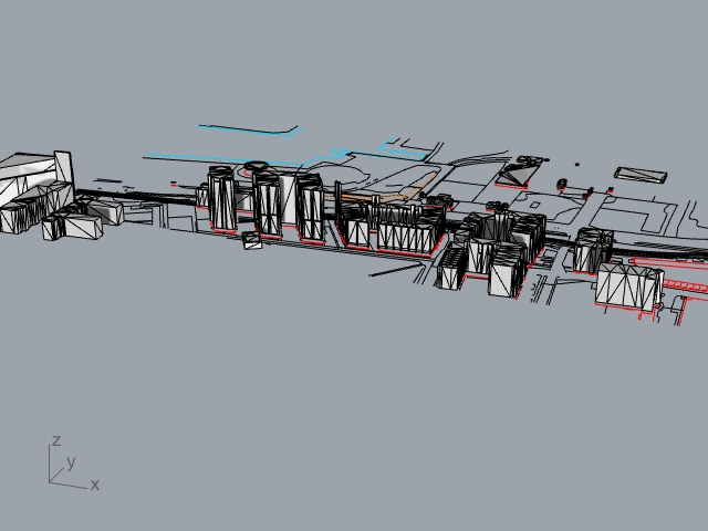
To begin the process of creating an axonometric view, I used a site model that has accurate dimensions that I wanted to create into an axonometric view.
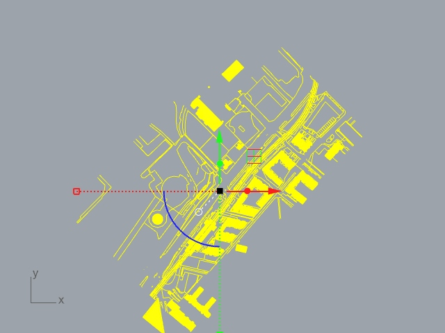
Step 1: Select and rotate the model in the top view
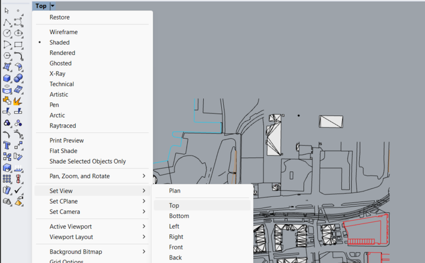
To start the first step in creating an axonometric, head over to the top view which can be changed by going over the settings on the canvas seen below.
Next, select the model by pressing “Ctrl + A” or clicking and dragging the model using the mouse or control pad.
Rotate the model
In the top view, you are then able to rotate the model by 45 degrees which is the first step in the process. So, type into the command line “Rotate”, click somewhere near the center of the model, then click on a reference point and type in “45” and “Enter” which will move the model.
Step 2: Shear the model
In order to shear the model in the right way, I went to the right view which is changed in the same way as if you were changing any other type of view. Go to the dropdown menu > set view > right.
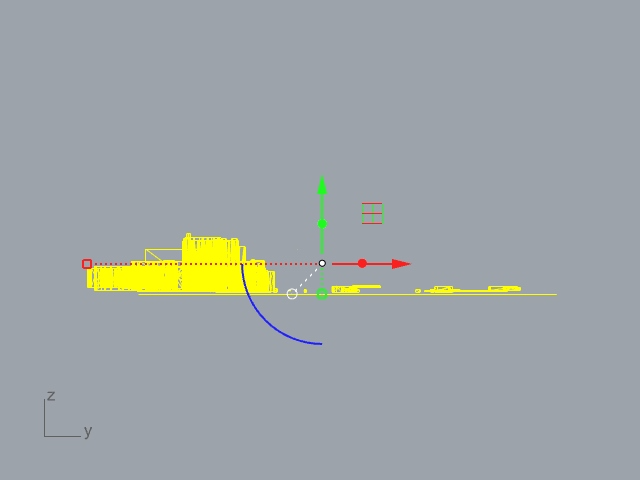
Afterwards, in the same right hand view, go over to the model and type in “Shear” and then select the model by pressing “Ctrl + A”.
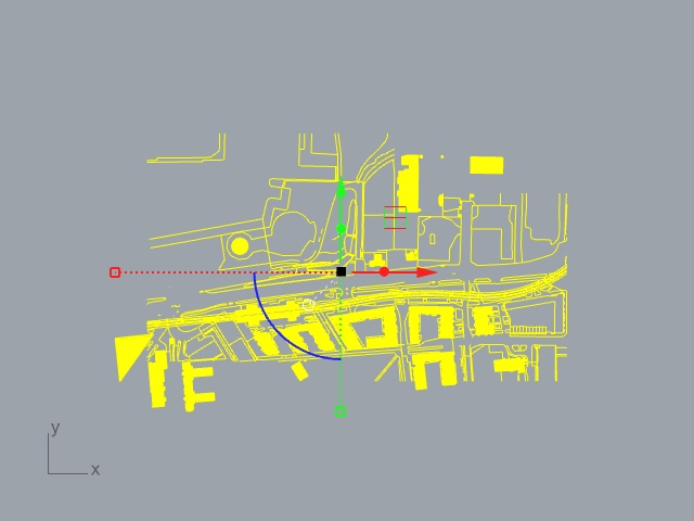
Then, click on the lowest point on the model, hold down shift and select a point directly on top of the lowest point and type in “-45” to the command line.
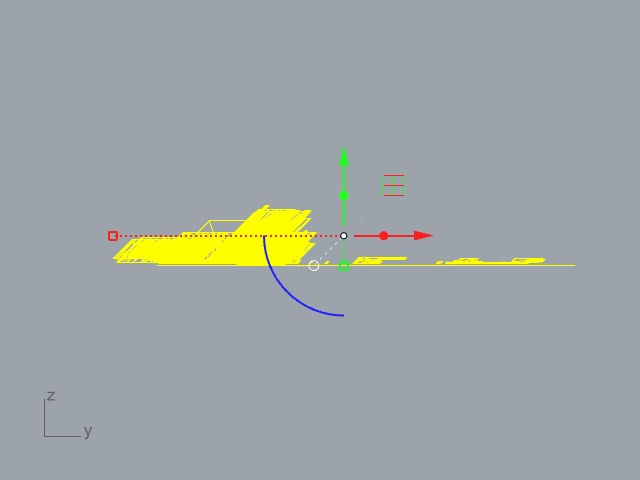
Step 3: Go back to the top view
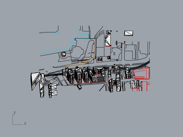
Now, your axonometric is done, all you need to do is go over to the top view and view the axonometric drawing which can then be saved and exported from this viewing angle.
From viewing the model in the pen view (Go to dropdown menu > pen), it is clearer to see the axonometric view.
How to save your axonometric projection
Now that I have my axonometric, I wanted to export it so that it can be edited later in another software such as Photoshop or Illustrator.
So here, I lay out how to turn the view that you see below into a line drawing that can be exported.
Step 1: Do the Make2D command
Type in to the command line “Make 2D”, press “Ctrl + A” or you can select the parts of the model you want to export individually. Once done, press “Enter”. There should be no change to your model so far.
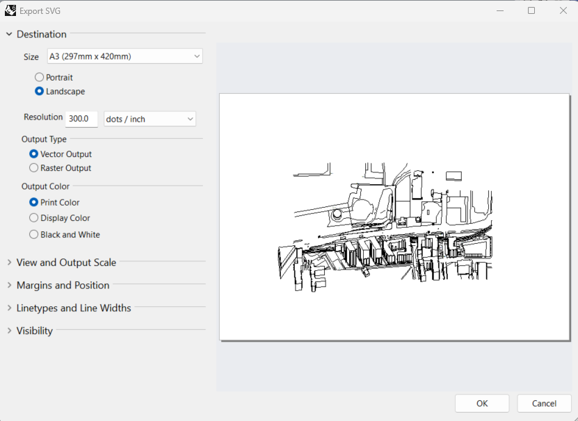
Step 2: Set up the right settings
The steps you did in step one should open up the settings box which is where you will choose the right settings for exporting.
You can see the chosen settings below but you want to make sure the “top” view is on for the view, the “View” is selected for the projection and that the “By output layers” is selected in options as well as the “Group output” checkbox.
Finally, you can call make2D whatever you want. In this case, I called it “axonometric”.
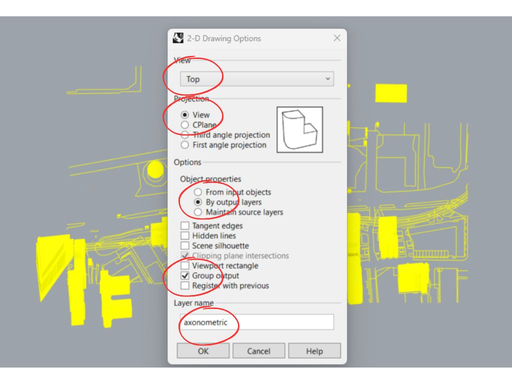
Once the setting has been finalized, click “OK” which will draw your Make2D projection you see as a plane.
Step 3: Export the lines
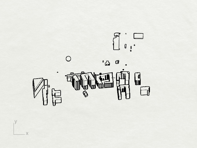
The first thing to understand after you have finished executing the setting in the make2D command is where the projection that has been drawn has ended up. So, scroll out, and try to find your axonometric projection in the top view.
As you can see, mine was quite a while away as my model wasn’t very near the origin.
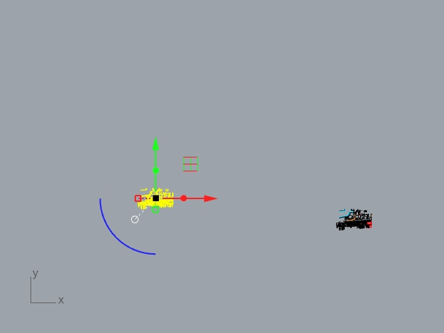
Do the export command
From here, make sure the Make2D axonometric projection is selected in yellow and do the command “Export” which will export the lines to a format you want.
Select the right file format
Then, select the file format that you want to export to be in. I chose Scalable Vector Graphics (.SVG) because this is perfect for importing into Illustrator.
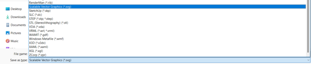
However, you may want to change this based on what software you will be importing your projection into.
Find the right scale for your axonometric view
If you have scaled your model correctly, this step shouldn’t be too hard. Simply select the paper size you want and toggle around with the setting in the section View and Output Scale to make sure you have the right settings.
Ensure the “Vector output” is selected rather than the “Raster output” and click “OK”.
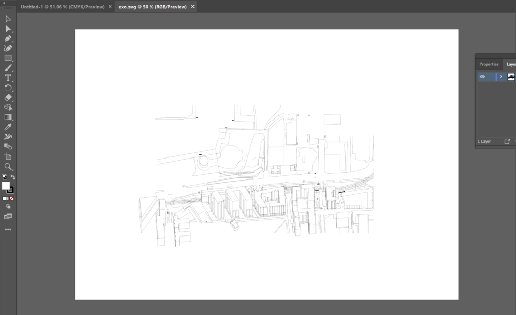
Step 4: Upload your file into Illustrator and Photoshop
Illustrator is the best tool I’ve found for editing lines and is why I’ve used the .SVG file format to export the drawing.
So, go to Illustrator, open up a document and then simply drag and drop your .SVG file from file explorer to begin editing.
What is the point of an axonometric drawing?
As an architecture student, you may come across different types of drawings and it is important to understand the difference between them.
One of the main advantages of axonometric drawings is that they provide a clear and comprehensive view of the building or space, making it easier to understand the overall design and layout.
This is particularly important when presenting your designs to clients or other stakeholders who may not have the technical knowledge to interpret traditional 2D drawings like sections so it is perfect for representing the final images of a project in an easy to comprehend format.
What is an isometric drawing?
Axonometric drawings can be either isometric, dimetric or trimetric, depending on the angle of the viewing plane, while isometric drawings are always at a 30-degree angle.
In architecture, isometric drawings are useful for showing building services such as HVAC ducts and plumbing systems, as well as furniture layouts and other interior details that an axonometric may not show in great detail.
What are the isometric, dimetric and trimetric projections?
Isometric, dimetric, and trimetric projections are all types of axonometric projections, which are used in technical drawing to represent three-dimensional objects in two dimensions.
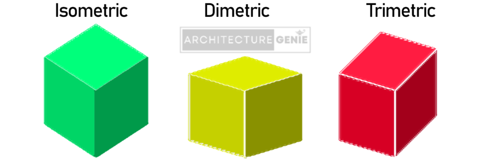
The choice of which axonometric projection to use depends on the specific needs of the project and the desired effect.
Each type of projection has its own strengths and weaknesses, and as an architecture student or professional, it is important to be familiar with all three types in order to choose the most appropriate one for each project.
What is an oblique drawing?
An oblique drawing is another type of three-dimensional drawing that is separate to axonometric and isometric drawings
They provide a more realistic and detailed view of the object by showing the first face of the object, in elevation, to scale and the rest of the object going off at an angle which is usually 30 degrees.