The most common method of creating technical drawings in Rhino 3D is the method of using Make2D. This is where you are able to make a 3D object in Rhino into a 2D line drawing and then export the file to a different software for further editing.
The great thing about this method is even if you have modeled an object that is very complex, you can cut out the shape and create a section at any point on the model. So if you have a building with a lot of furniture in it for instance, this will still be represented in the model.
Also, the more detailed the model is the better as you will even be able to note things such as the wall thicknesses and the details of the facade can all be recorded. If you aren’t sure how to create these types of details then learn how to do some basic architectural modeling exercises in Rhino here.
contents
How to create a technical drawing step by step
If you know you need to use the Make2D command to get the job done but you aren’t sure how to do it, follow the below steps that show you how to do it step by step.
You will need to have your model ready so you are able to cut it or represent a side of it such as an elevation.
Orient your model in the correct way
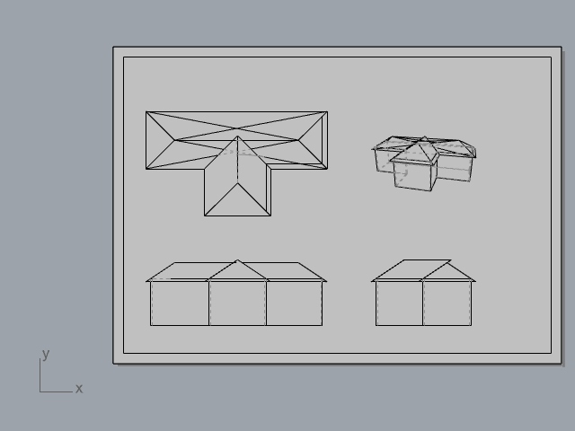
Below we have the model for the tutorial of creating a gable roof in rhino and we will use these to create a technical drawing from different angles using the software.
We will be using the wireframe view to keep things simpler so you can see exactly where the edges of the object are and you are better able to see how this translates as a 2D drawing.
In order to position the model, try to make sure that the grid that is underneath the model is parallel to the top of the model and you may also want to align the model at 90 degrees so the lattice of the grid lines up.
This makes it easier later on to represent the model in a format that looks easy on the eye and is able to be laid out in a well organized format.

Execute Make2D command
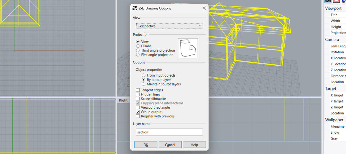
Next up, you can either do the “Make2D” command or you can go to “dimensions” which is one of the options at the very top of the dashboard in Rhino, then select “Make 2-D drawing” which will bring you to the same menu.
Then, you can select the individual objects that you want to turn into a 3D drawing or you can press “Ctrl + A” which will allow you to select everything in your Rhino canvas. This will leave you with the 2-D drawing options settings page that will appear like below.
Change the settings of the make 2D command
Depending on the type of projection you want to achieve, you may want to toggle with the setting. For the purpose of this tutorial, we will be using a third angle projection and also grouping the output so there are a range of angles on one page.
However, for the purpose of focusing on one type of technical drawing where you’d want the view of the model to be the main focus of the composition you are working on such as if you were doing a two point perspective drawing or an elevation, then you may want to just select “view” which will draw the model as it is seen from a certain perspective.
If this doesn’t make sense then be sure to check out our tutorials on this as the single view is needed to create a lot of drawings such as the axonometric drawing, plan oblique drawings and even to create sections which you will undoubtedly be needing to learn as an architect.
However, again, for the purpose of this tutorial, set up the below setting which will make sure the projection is split into four and there is a third angle projection which is what we’ll be working on throughout this tutorial.
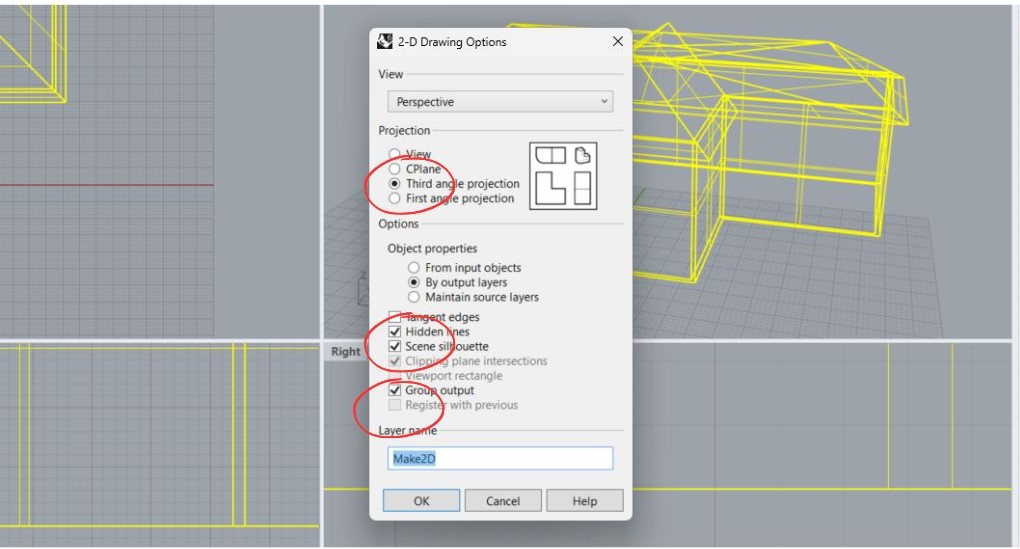
After you have set this up, press “OK” and wait for Rhino to do its magic. The settings circled in red are the ones you should be changing.
Turn off the visibility of the 3D model
Now that the Rhino model has worked and there is a Make2D projection, as you can see from the below view (which is being viewed from the top view). The original model clashes with the Make2D projection.
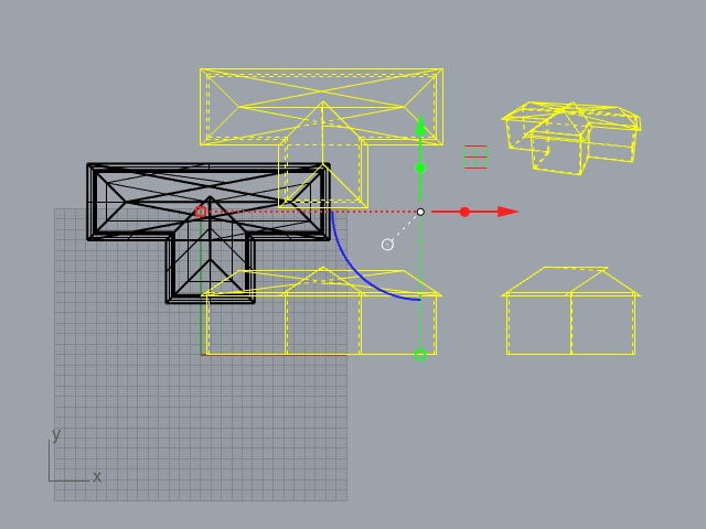
So, in order to fix this, select the house model which is in black (whatever model you are making a technical drawing for) and toggle its visibility off by using the light bulb icon on the Rhino dashboard as seen below.

If you want your model back to being visible at a later time you can select the light bulb that is full to turn it back on.
Create a new layout
Next, create a new layout for your Rhino model by going to view > layout > new layout which will allow everything to be easier edited as everything is contained within one box.

Delete unnecessary lines
As you look to export the object you’re working on, you may find there are lines that you don’t want to be included in your drawing. Hence, delete anything that doesn’t add to the quality of the drawing.
If you think there are too many dotted lines in the image then you could remove those or you can also add additional lines to your drawing too if you think there are some lines missing when there shouldn’t be. As you can see below, there are some lines removed and some that are added in.
Double click on the grayed out layout feature to begin editing lines and double click again once you have finished editing.
Change the thicknesses of certain lines
You may also wish to change the line weights of lines in Rhino so when you export the image there is some level of depth. This is perfect for highlighting what parts of the drawing are most important.
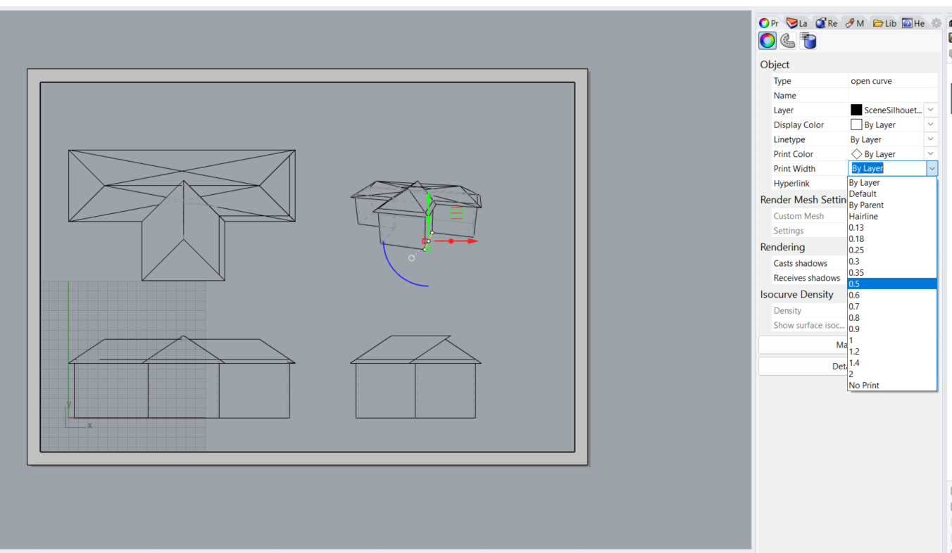
To do this select the line you want to change, select the “Print Width” dropdown then select the line weight that you desire.
You can also go to the “layers” panel and move different line weights into different layers if you want to get technical. To do this, select a line, do the command “ChangeLayer” then move the lines accordingly.
Add dimensions to your drawing
If you want the drawing to show certain lengths and be accurate and to scale with the 3D model you have designed, you will want to add in dimensions.
To do this click the “dimensions” panel in the top of the Rhino canvas and then click “Linear dimensions” from the drop down menu which will allow you to draw in dimensions where you want.
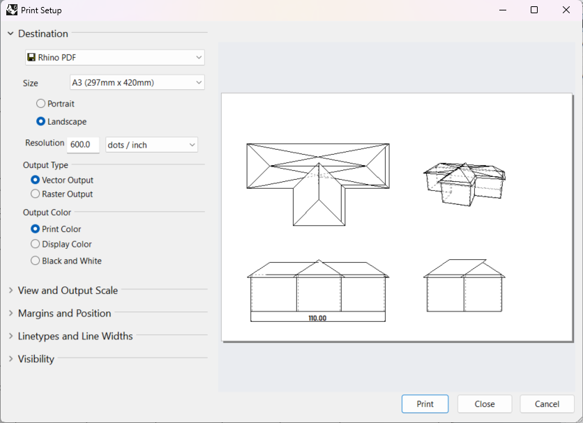
As you can see, the house is 110 meters long which is a bit large but you’d want to make sure your model is to scale before you add these dimensions as this demonstration is for tutorial purposes only.

Then, go to File > Properties > Annotation styles > Default which will allow you to change the color and the size of the font that you are using to display dimensions
Export the final format
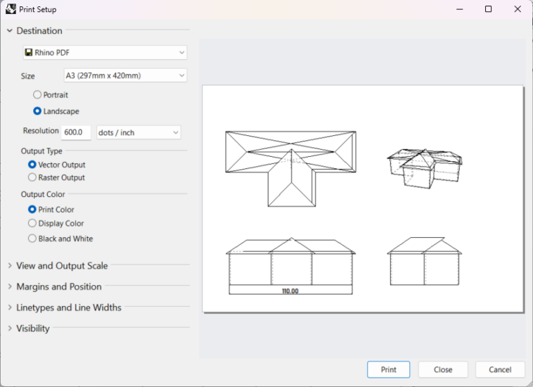
Once you have added all of the dimensions and changed the line widths of the image to suit you, you will then be able to add this to export the technical drawing by going to file > print then toggling the settings until you are happy with the result.
Because we have previously set up the layout for theprint, the composition of the drawing is perfect and there is no need to zoom in or zoom out as everything can be seen clearly in this case.
This is a rough job at a technical drawing but we have gone over all you need to bring the drawing up to scratch with your preferences. Do not be afraid to take this drawing into another software and add things like scale figures to make things appear more realistic.
When is the best time to start creating a technical drawing?
Typically, when you have finished modeling the building you want in Rhino and you want to represent it within plan, section or elevation is when you should start the process of creating a technical drawing.
It is best to have most if not all of the features already in a model as it makes things significantly easier rather than having to add these within the plan, section and elevation drawings individually. For instance, let’s say you wanted to add in some stairs to the model.