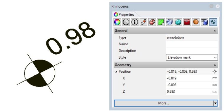
If you’re reading this article, you’re probably wondering how to go about making the right elevation markers on your technical drawings.
The process is different depending on what software you’re using so pay attention carefully as this tutorial goes over how to create an elevation specifically for Rhino 3D. To effortlessly set up your elevation markers, read on carefully and follow the steps as you do so.
To start things off, it is important to understand there isn’t just one way to add in an elevation marker. Unfortunately, the methods for adding in an elevation marker isn’t as straightforward as other softwares such as Revit as Rhino is predominantly used for modeling in 3D rather than creating 2D plans. Nonetheless, it can be done.
How to add the elevation marker in Rhino using VisualArq
First of all, download the VisualArq plugin from the food4rhino website here and begin familiarizing yourself with the setup of the plugin. You can also read more about the VisualArq plugin if you’re not sure what it is in our list of useful software plugins for Rhino 3D in this article.
The VisualArq plugin is also great for making elevations and sections as it updates the drawing as your model is edited in Rhino. This also makes it easy to create further drawings like oblique drawings and even axonometric drawings which all add to the diversity in an architectural portfolio.
Step 1: Define the features of the elevation marker
After you have downloaded VisualArq, you need to launch grasshopper in Rhino. This is where you will start building the script using the new plugins from the VisualArq download to create an elevation marker. Start with adding in the following inputs of the script which you can search for by double clicking the grasshopper dashboard and typing in their names.
- Plane
- Number slider (floating point)
- Number slider (integer)
- Hatch pattern
Step 2: Define how the elevation marker should look
To decide how the elevation marker looks, you need to focus on adding in the right outputs to the Rhino file you’re using too. This can be done by adding in the listed components which you can also find by double clicking on the Rhino canvas and writing these names:
- Text
- Hatch
- Geometry
Step 3: Fill in the grasshopper components
After you have put the right outputs on to the Rhino canvas, you need to fill in all of the components in between these outputs and the inputs to complete the script. Look at the below image and recreate the script in order to make an elevation marker that displays on Rhino viewport.
Once done, save the file somewhere on your hard drive as you will need this in the next step.
Step 4: Create a new grasshopper annotation
Now you have created the grasshopper script, you’d need to create the style in grasshopper. To do so, type into the command line “_VaAnnotationStyles” which opens a dialogue box that allows you to access the Grasshopper style wizard for VisualArq.
In this dialogue box, on the left side of the box will be a preview of the elevation marker that is being generated and on the right are the options you have to change.
Once happy with how your elevation marker looks, click on the grasshopper file you have created in previous steps in order to upload it by clicking the “browse” button and selecting the respective file.
Step 5: Configure the grasshopper style of the elevation marker
Next, in the same window as the previous step, you have the option to change the values of the dialogue box. This includes the name of the style, the definition units (meters or feet etc.). Finally, you can also change the Insert Plane.
The Insert Plane is the point in which the elevation marker will be placed. You can also modify this from the grasshopper file by adding in a point of input in the grasshopper file.
Step 6: Toggle geometry and parameters
As part of the importing process, you will need to choose whether the outputs of the grasshopper file (symbol, text and hatch) should be in the model of Rhino 3D or in the Plan. If it is in the model, then the elevation marker will be represented in 3D but if it is in plan it will only appear when there is a cutting plane placed on the model and it is intersected.
So, if you use the plan option this means the elevation marker will only be visible when you’re ready to work on the technical drawings using the VisualArq plugin.
Next, you will need to choose what parameters will be in the elevation marker and if you want to modify any of the settings away from their default state. This includes the axis length fact, the decimal precision, the offset distance, diameter, text size and pattern of the elevation marker.
In this step you can truly customize how you want the elevation marker to appear so you’re able to match it to the technical drawing you’re trying to create. For example, if you‘re going for more of a simple plan drawing, you may want to go with smaller text sizes and decimal precisions and the most modest pattern for the hatch.
Step 7: Insert the elevation marker
The final step of this process is to insert the elevation marker into the drawing you’re creating by clicking “finish”. It is useful to note you may still edit the elevation marker parameters if there are any settings you would like to change by clicking the annotation icon which is in the properties panel.
Similarly, to edit the style of the elevation marker, right click on the name of the style and click edit in the context menu that appears.

